|
在大二的时候,我们开的网络课程是学习锐捷的设备,经过两个学期的学习,对于路由器、交换机的基本配置,有了一定的基础。现在有机会接触了华为的设备,发现,锐捷设备的配置和华为设备的配置。还是有些区别的。比如在锐捷设备里,我们可以在特权模式下利用 show running-config 命令来查看基本配置信息,而在华为设备里,我们则要用display current-configuration 这一命令来查看基本配置信息,且在任何模式下都可以用这一命令来查看配置信息。 对网路只是有点了解的人都知道,在何种网络中使用何种路由协议是很重要的,而OSPF在动态路由协议中有着举足轻重的作用。经过一段的学习,对OSPF的一些基本配置有了一定的理解。今天,对OSPF的多区域配置做了一个简单的模拟,特发表此文。而遗憾的是,本实验,没有把每一步的配置代码粘下来,只把完成后的配置信息截取了下来,而由于时间的关系,我也不能再一条一条的写出来,对此表示由衷的歉意,希望广大同门能多多指教。 配置设备,拓扑是不能少的,下图就是一个简单的拓扑,为了说明问题,特地把RIP和stub都加在了这一实验里(由于设备有限,这里的r5和r6利用三层交换机来代替路由器)

从拓扑中我们可以看书,在r3与r4上都要要配置stub,由于我们做的是OSPF的多区域,,针对本实验,我们首先要进入 ospf配置模式,输入 stub cost 20 area 2 ,(cost后的20是符合条件的任意值,这一值再输入cost 后?一下就能看到)这一条命令就可以了。 在本实验中,我们看到,有OSPF 和RIP两种路由协议,所以如果不做任何配置的话,全网是不能互通的,所以我们要利用import命令来重分发来实现全网互通,针对本实验,由于ospf区域与rip相比较庞大,所以我们要把rip发布给ospf ,而只配置这一条,还是不能实现全网互通的,所以还要把ospf发布给rip,而刚已经说了,由于ospf区域与rip相比较庞大,我们不能把真个ospf区域的路由条目都发布给rip,这样的话,在匹配路由条目时要浪费很多的时间,所以我们可以做一条默认路由,ip route-table 0.0.0.0 0.0.0.0 null 0,而在华为设备里,null 0 是要自己创建的:interface null 0 来创建,然后把这一条静态路由发布给rip 有了拓扑以后,配置工作就好做多了,所有的参数数据都已在拓扑中标注的一清二楚的,接下来我们就照着拓扑着手配置了,各个设备的配置信息和路由表如下 R1
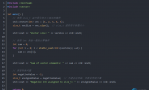
[r1] [r1]dis cu Now create configuration... Current configuration ! version 1.74 sysname r1 undo pos-server addr-switch firewall enable aaa-enable aaa accounting-scheme optional ! controller e1 0 ! interface Aux0 async mode flow link-protocol ppp ! interface Ethernet0 loopback ip address 192.168.1.1 255.255.255.0 ospf enable area 0.0.0.1 ! interface Ethernet1 ! interface Serial0 link-protocol ppp ! interface Serial1 link-protocol ppp ip address 192.168.2.1 255.255.255.0 ospf enable area 0.0.0.1 !

R2
[r2]dis cu Now create configuration... Current configuration ! version 1.74 sysname r2 undo pos-server addr-switch firewall enable aaa-enable aaa accounting-scheme optional ! interface Aux0 async mode flow link-protocol ppp ! interface Ethernet0 ! interface Ethernet1 ! interface Serial0 clock DTECLK1 link-protocol ppp ip address 192.168.3.1 255.255.255.0 ospf enable area 0.0.0.0 ! interface Serial1 clock DTECLK1 link-protocol ppp ip address 192.168.2.2 255.255.255.0 ospf enable area 0.0.0.1 !

R3
[r3]dis cu Now create configuration... Current configuration ! version 1.74 sysname r3 firewall enable aaa-enable aaa accounting-scheme optional ! interface Aux0 async mode flow link-protocol ppp ! interface Ethernet0 ip address 192.168.6.1 255.255.255.0 ! interface Serial0 link-protocol ppp ip address 192.168.3.2 255.255.255.0 ospf enable area 0.0.0.0 ! interface Serial1 clock DTECLK1 link-protocol ppp ip address 192.168.4.1 255.255.255.0 ospf enable area 0.0.0.2 ! interface Null0 ! quit rip undo summary network 192.168.6.0 import-route static cost 1 import-route direct cost 1 ! quit ! ospf enable stub cost 20 area 0.0.0.2 import-route direct import-route rip cost 10 ! quit ! quit ip route-static 0.0.0.0 0.0.0.0 Null 0 preference 60 ! return
[r3]

R4
[r4] [r4]dis cu Now create configuration... Current configuration ! version 1.74 sysname r4 undo pos-server addr-switch firewall enable aaa-enable aaa accounting-scheme optional ! interface Aux0 async mode flow link-protocol ppp ! interface Ethernet0 loopback ip address 192.168.5.1 255.255.255.0 ospf enable area 0.0.0.2 ! interface Ethernet1 ! interface Serial0 link-protocol ppp ! interface Serial1 link-protocol ppp ip address 192.168.4.2 255.255.255.0 ospf enable area 0.0.0.2 quit ospf enable stub cost 20 area 0.0.0.2 ! quit ! return
[r4]

R5
r5>sys <r5>system-view Enter system view, return to user view with Ctrl+Z. [r5]dis cu # sysname r5 # radius scheme system server-type huawei primary authentication 127.0.0.1 1645 primary accounting 127.0.0.1 1646 user-name-format without-domain
domain system radius-scheme system access-limit disable state active vlan-assignment-mode integer idle-cut disable self-service-url disable messenger time disable
domain default enable system # local-server nas-ip 127.0.0.1 key huawei # vlan 1 # vlan 10 # vlan 20 # interface Vlan-interface10 ip address 192.168.6.2 255.255.255.0 # interface Vlan-interface20 ip address 192.168.7.1 255.255.255.0 # interface Aux0/0 # interface Ethernet0/1 port access vlan 10 #
interface Ethernet0/24
port access vlan 20 # interface NULL0 # rip undo summary network 192.168.6.0 network 192.168.7.0 # user-interface aux 0 user-interface vty 0 4 # return

R6
[r6]dis cu # sysname r6 # radius scheme system server-type huawei primary authentication 127.0.0.1 1645 primary accounting 127.0.0.1 1646 user-name-format without-domain
domain system radius-scheme system access-limit disable state active idle-cut disable self-service-url disable messenger time disable
domain default enable system # local-server nas-ip 127.0.0.1 key huawei # vlan 1 # vlan 20 # interface Vlan-interface20 ip address 192.168.7.2 255.255.255.0 # interface Aux0/0
interface Ethernet0/24
port access vlan 20 # interface NULL0 # interface LoopBack1 ip address 192.168.8.1 255.255.255.0 # rip undo summary network 192.168.7.0 network 192.168.8.0 # user-interface aux 0 user-interface vty 0 4 # return

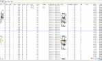
配置完毕后,就要进行测试了,下面就是本实验的测试结果:


由此看来,本实验一成功了。我刚真正的去学设配,希望广大同门多多指教!!!
|  QQ群⑧:
QQ群⑧:


 窥视卡
窥视卡 雷达卡
雷达卡 发表于 2013-3-11 09:43:10
 提升卡
提升卡 置顶卡
置顶卡 沉默卡
沉默卡 喧嚣卡
喧嚣卡 变色卡
变色卡 千斤顶
千斤顶 显身卡
显身卡