一、实验目标
- 掌握交换机Tag VLAN 的配置;
- 掌握三层交换机基本配置方法;
- 掌握三层交换机VLAN路由的配置方法;
- 通过三层交换机实现VLAN间相互通信;
二、实验背景
某企业有两个主要部门,技术部和销售部,分处于不同的办公室,为了安全和便于管理,对两个部门的主机进行了VLAN的划分,技术部和销售部分处于不同的VLAN。现由于业务的需求,需要销售部和技术部的主机能够相互访问,获得相应的资源,两个部门的交换机通过一台三层交换机进行了连接。
三、技术原理
三层交换机具备网络层的功能,实现VLAN间相互访问的原理是:利用三层交换机的路由功能,通过识别数据包的IP地址,查找路由表进行选路转发。三层交换机利用直连路由可以实现不同VLAN之间的互相访问。三层交换机给接口配置IP地址,采用SVI(交换虚拟接口)的方式实现VLAN间互连。SVI是指为交换机中的VLAN创建虚拟接口,并且配置IP地址。
四、实验步骤
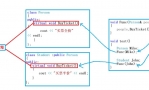
实验拓扑
1、在二层交换机上配置VLAN 2、VLAN 3,分别将端口2、端口3划到VLAN 2、VLAN 3; 2、将二层交换机与三层交换机相连的端口Fa0/1定义为Tag VLAN模式; Switch>en
Switch#conf t
Enter configuration commands, one per line. End with CNTL/Z.
Switch(config)#vlan 2
Switch(config-vlan)#exit
Switch(config)#vlan 3
Switch(config-vlan)#exit
Switch(config)#interface fa0/2
Switch(config-if)#switchport access vlan 2
Switch(config-if)#exit
Switch(config)#interface fa0/3
Switch(config-if)#switchport access vlan 3
Switch(config-if)#exit
Switch(config)#interface fa0/1
Switch(config-if)#switchport mode trunk
%LINEPROTO-5-UPDOWN: Line protocol on Interface FastEthernet0/1, changed state to down
%LINEPROTO-5-UPDOWN: Line protocol on Interface FastEthernet0/1, changed state to up
Switch(config-if)#
3、在三层交换机上配置VLAN 2、VLAN 3,分别将端口2、端口3划到VLAN 2、VLAN 3;
Switch>en
Switch#conf t
Enter configuration commands, one per line. End with CNTL/Z.
Switch(config)#vlan 2
Switch(config-vlan)#exit
Switch(config)#vlan 3
Switch(config-vlan)#exit
Switch(config)#interface fa0/2
Switch(config-if)#switchport access vlan 2
Switch(config-if)#exit
Switch(config)#interface fa0/3
Switch(config-if)#switchport access vlan 3
Switch(config-if)#exit
Switch(config)#
4、设置三层交换机VLAN间通信,创建VLAN 2、VLAN 3的虚拟接口,并配置虚拟接口VLAN 2、VLAN 3的IP地址;
Switch(config)#interface vlan 2 //创建 VLAN 2 的虚拟接口
Switch(config-if)#
%LINK-5-CHANGED: Interface Vlan2, changed state to up
%LINEPROTO-5-UPDOWN: Line protocol on Interface Vlan2, changed state to up
Switch(config-if)#ip address 192.168.1.1 255.255.255.0 //配置虚拟接口 VLAN 2 的IP地址
Switch(config-if)#no shutdown
Switch(config-if)#exit
Switch(config)#interface vlan 3 //创建 VLAN 2 的虚拟接口
Switch(config-if)#
%LINK-5-CHANGED: Interface Vlan3, changed state to up
%LINEPROTO-5-UPDOWN: Line protocol on Interface Vlan3, changed state to up
Switch(config-if)#ip address 192.168.2.1 255.255.255.0 //配置虚拟接口 VLAN 2 的IP地址
Switch(config-if)#no shutdown
Switch(config-if)#end
Switch#
5、查看三层交换机路由表
Switch#show ip route
Codes: C - connected, S - static, I - IGRP, R - RIP, M - mobile, B - BGP
D - EIGRP, EX - EIGRP external, O - OSPF, IA - OSPF inter area
N1 - OSPF NSSA external type 1, N2 - OSPF NSSA external type 2
E1 - OSPF external type 1, E2 - OSPF external type 2, E - EGP
i - IS-IS, L1 - IS-IS level-1, L2 - IS-IS level-2, ia - IS-IS inter area
* - candidate default, U - per-user static route, o - ODR
P - periodic downloaded static route
Gateway of last resort is not set
C 192.168.1.0/24 is directly connected, Vlan2
C 192.168.2.0/24 is directly connected, Vlan3
Switch#
6、将VLAN 2、VLAN 3下的主机默认网关分别设置为相应虚拟接口的IP地址;
五、验证
打开PC1 Command Prompt
Packet Tracer PC Command Line 1.0
PC>ipconfig
IP Address......................: 192.168.1.2
Subnet Mask.....................: 255.255.255.0
Default Gateway.................: 192.168.1.1
PC>ping 192.168.1.3
Pinging 192.168.1.3 with 32 bytes of data:
Reply from 192.168.1.3: bytes=32 time=187ms TTL=128
Reply from 192.168.1.3: bytes=32 time=93ms TTL=128
Reply from 192.168.1.3: bytes=32 time=110ms TTL=128
Reply from 192.168.1.3: bytes=32 time=93ms TTL=128
Ping statistics for 192.168.1.3:
Packets: Sent = 4, Received = 4, Lost = 0 (0% loss),
Approximate round trip times in milli-seconds:
Minimum = 93ms, Maximum = 187ms, Average = 120ms
PC>ping 192.168.2.2
Pinging 192.168.2.2 with 32 bytes of data:
Request timed out.
Reply from 192.168.2.2: bytes=32 time=188ms TTL=127
Reply from 192.168.2.2: bytes=32 time=112ms TTL=127
Reply from 192.168.2.2: bytes=32 time=125ms TTL=127
Ping statistics for 192.168.2.2:
Packets: Sent = 4, Received = 3, Lost = 1 (25% loss),
Approximate round trip times in milli-seconds:
Minimum = 112ms, Maximum = 188ms, Average = 141ms
PC>ping 192.168.2.3
Pinging 192.168.2.3 with 32 bytes of data:
Request timed out.
Reply from 192.168.2.3: bytes=32 time=125ms TTL=127
Reply from 192.168.2.3: bytes=32 time=78ms TTL=127
Reply from 192.168.2.3: bytes=32 time=64ms TTL=127
Ping statistics for 192.168.2.3:
Packets: Sent = 4, Received = 3, Lost = 1 (25% loss),
Approximate round trip times in milli-seconds:
Minimum = 64ms, Maximum = 125ms, Average = 89ms
|  QQ群⑧:
QQ群⑧:


 窥视卡
窥视卡 雷达卡
雷达卡 发表于 2016-3-31 09:12:17

 提升卡
提升卡 置顶卡
置顶卡 沉默卡
沉默卡 喧嚣卡
喧嚣卡 变色卡
变色卡 千斤顶
千斤顶 显身卡
显身卡