|
|

At long last, we can finally integrate VMware Fusion with GNS3. VMware Workstation for Windows and Linux has had this capability for quite some time, but Mac users were limited to VirtualBox, QEMU and Parallels for GNS3 integration. Not to take anything away from those virtualization products, but VMware is the virtualization standard in regards to broad industry support and compatibility.
The following components were used for this tutorial:
- Mac OS X 10.8 (also tested with Mac OS X 10.9)
- VMware Fusion 6.0 Professional
- GNS3
- TunTap
This tutorial assumes you have, at the very least, a basic amount of experience with each of the listed components. You can refer to my previous post Install and configure GNS3 with TunTap on the Mac for the GNS3 and TunTap elements. Another prerequisite is that all components are installed and set with a base configuration.
1. VMware Fusion
VMware Fusion 6 is a hard requirement for this tutorial. VMware has made modifications to the VMnet virtual switches (in version 6) to allow Ethernet bridging with other virtual network interfaces (e.g. TAP). If you use this tutorial with version 5 or below, you may encounterkernel panics on your Mac. You've been warned. :-)
I'm also using VMware Fusion 6.0 Professional in my setup. The non-Professional edition does not include the GUI Network Editor. A possible solution for the "vanilla" edition of VMware Fusion 6.0 is the UBER Network Fuser tool by Nicholas Weaver. I haven't tested the tool with VMware Fusion 6.0, so a little research on your part may be in order.
# 1.1 Virtual Network Switches
Our network configuration will use two host-only network switches. A host-only network (switch) is a network that is completely contained within the host computer. Host-only networking provides a network connection between the virtual machine and the host system by using a virtual network adapter that is visible on the host operating system. vmnet1 is available by default and is listed as Private to my Macin the GUI. Let's now add the other one.
- Open the Preferences window for VMware Fusion Professional.
- Select Network.
- Select the + symbol to add a new virtual switch. In my example, vmnet5 is added. As the following screenshot shows, we will leave theAllow virtual machines on this network to connect to external networks (using NAT) and Provide addresses on this network via DHCP options unchecked.
- Select the Apply button to save the setting, then close the Preferences window.

FYI: vmnet1 and vmnet8 are the default host-only and NAT virtual switches, respectively. vmnet8 is listed as Share with my Mac in the GUI.
We can list all network interfaces (physical and virtual) with the ifconfig command from the terminal.
$ ifconfig
# 1.2 Virtual Machines
This section will assume you've already installed the operating system in each of your virtual machines, or you have opted to import a virtual appliance. Just verify a vNIC is connected to the correct virtual network (switch). In my example, I have both a Windows and Linux virtual machine. The Windows VM is linked to the vmnet1 switch and the Linux VM will use vmnet5.

After each virtual machine's hardware profile is set, we can go ahead and start the VMs.
Set the network configuration in each operating system:
- Static IP Address
- Subnet Mask
- Gateway
- DNS Server(s)
My configuration for each VM:

2. GNS3
With the VMware Fusion section complete, we can now focus on GNS3. The remainder of the tutorial will be referencing this network diagram:

Go ahead and add the GNS3 objects to a new project. My configuration has R1 using a Cisco 3725 IOS image but feel free to use any GNS3-compatible IOS image for your virtual router. SW1 and SW2 are simple GNS3 Ethernet switches. The VMs are Host objects (not VirtualBox guest), and the object that looks like a cloud is ... wait for it ... a Cloud object.
# 2.1 Cloud and Hosts
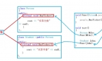
We need to configure each of the Cloud and Host objects before we wire them to the switches. Each object will be using a TAP virtual network interface. Let's start with the Cloud object.
- Right-click the Cloud object.
- Select Configure.
- Select the subnode (ex. C1).
- Select NIO TAP.
- Enter /dev/tap0 into the top field.
- Select the Add button to add the interface.
- Select the Apply button to save the setting.
- Then select the OK button to close the window.

Repeat the steps for each of the Host objects. Just substitute the tapX value. The Windows VM will use /dev/tap1 and the Linux VM will use /dev/tap2. These are labeled in the network diagram screenshot.
Connect all the objects with Fast Ethernet links.
By linking the Cloud and Host objects with the switches, it should have brought up the TAP network interfaces on the physical Mac host. Let's check. Run the following commands from the terminal:
$ ifconfig tap0 tap0: flags=8842<BROADCAST,RUNNING,SIMPLEX,MULTICAST> mtu 1500 ether 02:e9:2d:82:4d:f8 open (pid 5333) $ ifconfig tap1 tap1: flags=8842<BROADCAST,RUNNING,SIMPLEX,MULTICAST> mtu 1500 ether ee:47:b5:07:63:ea open (pid 5333) $ ifconfig tap2 tap2: flags=8842<BROADCAST,RUNNING,SIMPLEX,MULTICAST> mtu 1500 ether 0e:6d:9b:0e:f9:cf open (pid 5333)
# 2.2 R1 Router
Start the R1 router. Emulate a console connection by establishing a telnet session to the virtual device. In my configuration, R1 (Dynamips) is listening on port 2101, so I run the following command in the terminal:
$ telnet localhost 2101
We now need to set the network configuration for the Fast Ethernet interfaces in IOS. In my example:
R1# conf t R1(config)# int f0/0 R1(config-if)# ip addr 10.11.1.254 255.255.255.0 R1(config-if)# no shut R1(config-if)# int f0/1 R1(config-if)# ip addr 172.16.195.254 255.255.255.0 R1(config-if)# no shut R1(config-if)# end R1# copy run start
Verify the configuration and state of the Fast Ethernet interfaces.
R1# sh run | sec int interface FastEthernet0/0 ip address 10.11.1.254 255.255.255.0 duplex auto speed auto interface FastEthernet0/1 ip address 172.16.195.254 255.255.255.0 duplex auto speed auto R1# sh ip int br Interface IP-Address OK? Method Status Protocol FastEthernet0/0 10.11.1.254 YES manual up up FastEthernet0/1 172.16.195.254 YES manual up up
3. Ethernet Bridge
So now the big question is: How do we integrate our Windows and Linux VMs with the GNS3 environment? The answer is by creating an Ethernet bridge. This will essentially bind two separate virtual network segments (vmnetX and tapX) into a single virtual network interface attached to the Mac host. We will be creating two bridge interfaces. One for the Windows VM and the other for the Linux VM.
# 3.1 Bridge for Windows VM
We first need to clear the IP configuration for the vmnet1 virtual network interface before adding it as a member to the first bridge interface. Run the following from the terminal:
$ sudo ifconfig vmnet1 down $ sudo ifconfig vmnet1 inet delete
Create the first bridge interface for the Windows VM.
$ sudo ifconfig bridge0 create
Add the member network interfaces (vmnet1 and tap1) to the bridge.
$ sudo ifconfig bridge0 addm vmnet1 $ sudo ifconfig bridge0 addm tap1
Bring the bridge interface up.
$ sudo ifconfig bridge0 up
Verify the bridge0 configuration.
$ ifconfig bridge0 bridge0: flags=8863<UP,BROADCAST,SMART,RUNNING,SIMPLEX,MULTICAST> mtu 1500 ether ac:de:48:ed:da:5a Configuration: priority 0 hellotime 0 fwddelay 0 maxage 0 ipfilter disabled flags 0x2 member: vmnet1 flags=3<LEARNING,DISCOVER> port 7 priority 0 path cost 0 member: tap1 flags=3<LEARNING,DISCOVER> port 14 priority 0 path cost 0 Address cache (max cache: 100, timeout: 1200):
# 3.2 Bridge for Linux VM
Just like with vmnet1, we need to clear the IP configuration for the vmnet5 virtual network interface before adding it as a member to the second bridge interface. Run the following from the terminal:
$ sudo ifconfig vmnet5 down $ sudo ifconfig vmnet5 inet delete
Create the second bridge interface for the Linux VM.
$ sudo ifconfig bridge1 create
Add the member network interfaces (vmnet5 and tap2) to the bridge.
$ sudo ifconfig bridge1 addm vmnet5 $ sudo ifconfig bridge1 addm tap2
Bring the bridge interface up.
$ sudo ifconfig bridge1 up
Verify the bridge1 configuration.
$ ifconfig bridge1 bridge1: flags=8863<UP,BROADCAST,SMART,RUNNING,SIMPLEX,MULTICAST> mtu 1500 ether ac:de:48:6d:28:37 Configuration: priority 0 hellotime 0 fwddelay 0 maxage 0 ipfilter disabled flags 0x2 member: vmnet5 flags=3<LEARNING,DISCOVER> port 9 priority 0 path cost 0 member: tap2 flags=3<LEARNING,DISCOVER> port 15 priority 0 path cost 0 Address cache (max cache: 100, timeout: 1200): c2:0:14:d5:0:1 tap2 1158 flags=0<>
4. Tap0 Interface
The tap0 interface will not be part of a bridge interface, but we still need to set the IP configuration for it as it will be a node interface on the 10.11.1.0/24 network.
$ sudo ifconfig tap0 inet 10.11.1.1/24 up
5. Testing and Verification
At this stage, we should be ready to do some basic connectivity testing.
Ping the Linux VM from the Windows VM.
C:\> ping 172.16.195.11 Pinging 172.16.195.11 with 32 bytes of data: Reply from 172.16.195.11: bytes=32 time=1ms TTL=64 Reply from 172.16.195.11: bytes=32 time<1ms TTL=64 Reply from 172.16.195.11: bytes=32 time<1ms TTL=64 Reply from 172.16.195.11: bytes=32 time<1ms TTL=64 Ping statistics for 172.16.195.11: Packets: Sent = 4, Received = 4, Lost = 0 (0% loss), Approximate round trip times in milli-seconds: Minimum = 0ms, Maximum = 1ms, Average = 0ms
Ping the R1 f0/1 interface (default gateway) from the Windows VM.
C:\> ping 172.16.195.254 Pinging 172.16.195.254 with 32 bytes of data: Reply from 172.16.195.254: bytes=32 time=16ms TTL=255 Reply from 172.16.195.254: bytes=32 time=9ms TTL=255 Reply from 172.16.195.254: bytes=32 time=6ms TTL=255 Reply from 172.16.195.254: bytes=32 time=5ms TTL=255 Ping statistics for 172.16.195.254: Packets: Sent = 4, Received = 4, Lost = 0 (0% loss), Approximate round trip times in milli-seconds: Minimum = 5ms, Maximum = 16ms, Average = 9ms
Ping the R1 f0/0 interface from the Windows VM.
C:\> ping 10.11.1.254 Pinging 10.11.1.254 with 32 bytes of data: Reply from 10.11.1.254: bytes=32 time=17ms TTL=255 Reply from 10.11.1.254: bytes=32 time=9ms TTL=255 Reply from 10.11.1.254: bytes=32 time=6ms TTL=255 Reply from 10.11.1.254: bytes=32 time=7ms TTL=255 Ping statistics for 10.11.1.254: Packets: Sent = 4, Received = 4, Lost = 0 (0% loss), Approximate round trip times in milli-seconds: Minimum = 6ms, Maximum = 17ms, Average = 9ms
Everything looks good so far. Let's now try to ping the tap0 network interface.
C:\> ping 10.11.1.1 Pinging 10.11.1.1 with 32 bytes of data: Request timed out. Request timed out. Request timed out. Request timed out. Ping statistics for 10.11.1.1: Packets: Sent = 4, Received = 0, Lost = 4 (100% loss),
Now, why did it fail? Let's break it down logically. The Windows VM can ping each interface on its own subnet and also the R1 f0/0 interface on the remote 10.11.1.0/24 subnet, but for some reason it doesn't receive an ICMP Echo reply from tap0. Remember that routing is a "two-way street". The packets may get to the destination, but do they know how to get back? R1 knows about both subnets as they are direct (connected) routes in the routing table, so let us think from the viewpoint of the tap0 interface on the Mac. Does it know how to get to the remote subnet? Let's check the routing table, on the Mac, for the 172.16.195.0 network entry. Run the following command from the terminal:
$ netstat -rn | grep 172.16.195
Nothing. Therein lies the problem. The Mac needs a route for the remote 172.16.195.0 subnet. Create the static route by running the following command from the terminal:
$ sudo route -nv add -net 172.16.195.0 10.11.1.254 u: inet 172.16.195.0; u: inet 10.11.1.254; RTM_ADD: Add Route: len 132, pid: 0, seq 1, errno 0, flags:<UP,GATEWAY,STATIC> locks: inits: sockaddrs: <DST,GATEWAY,NETMASK> 172.16.195.0 10.11.1.254 (0) 0 ffff ff add net 172.16.195.0: gateway 10.11.1.254
Verify.
$ netstat -rn | egrep 'Use|172.16.195' Destination Gateway Flags Refs Use Netif Expire 172.16.195/24 10.11.1.254 UGSc 0 0 tap0
Let's ping the tap0 interface again from the Windows VM.
C:\> ping 10.11.1.1 Pinging 10.11.1.1 with 32 bytes of data: Reply from 10.11.1.1: bytes=32 time=35ms TTL=63 Reply from 10.11.1.1: bytes=32 time=12ms TTL=63 Reply from 10.11.1.1: bytes=32 time=15ms TTL=63 Reply from 10.11.1.1: bytes=32 time=13ms TTL=63 Ping statistics for 10.11.1.1: Packets: Sent = 4, Received = 4, Lost = 0 (0% loss), Approximate round trip times in milli-seconds: Minimum = 12ms, Maximum = 35ms, Average = 18ms
We should now have full connectivity among all devices in our virtual network.
6. No Man Is An Island
Let's take this a step further. Let's extend the reach of our virtual network to the Internet. We have at least two different methods of implementing this. We can either configure NAT on the R1 router (and also have the physical Mac host perform routing) or have our physical Mac host perform both the NAT and IP routing process. We will use the latter method.
Note: A wired (i.e., no Wi-Fi) Ethernet connection is required. As newer Mac laptops don't have a physical Ethernet port, the StarTech USB31000S (Black) | USB31000SW (White) is a viable solution.
# 6.1 IP Routing
You may be thinking: How can my Mac route packets with only a single, active, physical network interface with a single IP address? Think virtual. The tap0 network interface is the link to our virtual network. It is the "other arm", so to speak. Get the current IP Routing configuration by running the following command in the terminal:
$ sysctl -a | grep ip.forwarding net.inet.ip.forwarding: 0
If the value is 0, enable IP forwarding. When IP forwarding is enabled, the operating system kernel will act as a router.
$ sudo sysctl -w net.inet.ip.forwarding=1 net.inet.ip.forwarding: 0 -> 1
# 6.2 NAT
Start the Network Address Translation (NAT) daemon with these options. The interface parameter value being the wired Ethernet network interface that accesses the Internet.
$ sudo natd -interface en0 -use_sockets -same_ports -unregistered_only -dynamic -clamp_mss
Verify the NAT daemon status.
$ ps aux | grep natd | grep en0 root 7424 0.0 0.0 2432924 416 ?? Ss 4:31PM 0:00.48 natd -interface en0 -use_sockets -same_ports -unregistered_only -dynamic -clamp_mss
# 6.3 Firewall
The IP firewall will also need to be enabled. Is the firewall already enabled?
$ sysctl -a | grep ip.fw.en net.inet.ip.fw.enable: 1
If the value is 0, we can enable it with the sysctl utility.
$ sudo sysctl -w net.inet.ip.fw.enable=1
Add a firewall rule for the NAT daemon. Remember to modify the network interface value following the via token if need be.
$ sudo ipfw add divert natd ip from any to any via en0 00100 divert 8668 ip from any to any via en0
Verify the firewall rule has been added.
$ sudo ipfw show 00100 10 622 divert 8668 ip from any to any via en0 65535 10390254 10716213934 allow ip from any to any
# 6.4 R1 Router
IOS for R1 will also need to be configured before R1 and the VMs can access the Internet.
Emulate a console connection by establishing a telnet session to the virtual device. In my configuration, R1 is listening on port 2101, so I run the following command in the terminal:
$ telnet localhost 2101
Enable DNS translation and set to the Google Public DNS.
R1# conf t R1(config)# ip domain-lookup R1(config)# ip name-server 8.8.8.8
And finally, add a static default route for any unknown destination. Use the tap0 IP address for the next-hop IP address value. Also, save the configuration.
R1(config)# ip route 0.0.0.0 0.0.0.0 10.11.1.1 R1(config)# end R1# copy run start
# 6.5 One More Test
The moment of truth.
# mtr www.google.com  |
|
 QQ群⑧:
QQ群⑧:


 窥视卡
窥视卡 雷达卡
雷达卡 发表于 2018-6-6 11:24:44
 提升卡
提升卡 置顶卡
置顶卡 沉默卡
沉默卡 喧嚣卡
喧嚣卡 变色卡
变色卡 千斤顶
千斤顶 显身卡
显身卡