|
|
此大师之做,水平有限不敢胡乱翻译,建议精读
sign:http://blogs.technet.com/b/jhoward/archive/2008/06/16/how-does-basic-networking-work-in-hyper-v.aspx
While it is possible to create some complex networking environments in Hyper-V, the basic concepts are relatively straight forward. This post walks some simple scenarios and how the main components operate in terms of the flow of data.
Let’s start by setting a level playing field and a “best practice”.
- When adding the Hyper-V role in a full installation of Windows Server 2008, you have the option to create one or more external virtual network switches. (This option is not available in server core installations of Windows Server 2008). I’m going to assume that no external virtual network switches were created during installation, and the Hyper-V role is enabled.
- Our recommendation, in a simple deployment, is to have at least two physical NICs in a physical machine– one (or more) dedicated to the physical machine, and one (or more) for virtual machines. The reason will become obvious as you work through this post.
To constrain the starting point, I’m assuming (for simplicity, not by recommendation) the physical machine contains a single physical NIC.
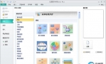
If you open Network Connections (Start/Control Panel/Network and Sharing Center, or Start ncpa.cpl), you would see something like below – a single connection.

And to get some more information, I’ve used View/Detail in the next screenshot:

Let’s look at the network bindings by selecting the NIC, right-clicking and choosing properties. Notice that (in this simple example), all protocols are bound to the NIC except the Microsoft Virtual Network Switch Protocol.

Let’s see what changes when we create an External Virtual Network Switch. Here, I’m using Hyper-V Manager, selected Virtual Network Manager, added an External Virtual Network named “Test External Network” and selected my single Physical NIC in the drop-down. On hitting apply, you will get a warning that you may temporarily lose network connectivity while we reconfigure everything.


Now let’s go back to Network Connections and see what has changed.

Notice that there are now two network connections listed, but with different Device Names. Let’s look at the top one first which has the device name matching the type of physical device and open the properties to examine the bindings.

Notice that nothing is bound except the Microsoft Virtual Network Switch Protocol. Now let’s open the other bottom one which has the device name matching the name I entered when creating the external virtual network switch, “Test External Network”.

Notice that everything is bound except the Microsoft Virtual Network Switch Protocol.
So what does this mean? Well, to explain, let’s take a physical switch. Let’s pretend it’s a simple “unmanaged” switch – the type you can buy as a commodity $30 device down at your local computer store. It typically has 8 ports on it. You can’t add ports to it. You can’t take them away. It has, and will only ever have 8 ports.
Now go “virtual” for one moment and in your mind create a Virtual network switch. It’s still conceptually a box with ports. Where things get a little different is that in the virtual world, ports can be added and removed dynamically as needed, without the need for a soldering iron.
Now let’s map this into what we just did above.
- We created a new virtual network switch with two ports.
- We added another NIC to the physical computer (it just happens that it’s a Virtual NIC, not a physical NIC)
- We logically labeled the switch “Test External Network”.
- We ran a couple of bits of “virtual” network plumbing
- A pseudo virtual CAT5 cable from the virtual network switch to the physical NIC. (*)
- A virtual CAT5 cable from the Virtual NIC into the virtual network switch
- We re-jigged some network bindings.
(*) Bear with me on this point – it will make sense soon why there’s some software magic in this bit of virtual cable. Obviously words are nowhere as easy to understand as a picture. Here’s what we’ve done:

On the top right, there is a networking application. Let’s assume it’s “ping”. What ping does is send a IP packet out to somewhere, and waits for a response to come back. With some gross over-simplification, here’s the steps:
- Ping uses the Windows networking stack to determine where the IP protocol is bound. There is only one choice – it’s on the Virtual NIC.
- An IP packet is sent down to the networking stack bound to the Virtual NIC. This is the flow labeled “1”.
- The Virtual NIC has a bit of virtual CAT5 cable plugged into it. The virtual NIC does what any physical NIC would do: Put the packet on the (virtual) wire. This is the flow labeled “2”.
- The other end of the virtual CAT5 cable is plugged into a (virtual) port on the Virtual Network Switch called “Test External Network”. The packet appears at the switch port.
- (Simplying again…) The Virtual Network Switch does what a physical counterpart would do and routes the packet to its destination. Without going into the detail of routing and learning algorithms, suffice to say it makes the packet makes it’s way to the other virtual port on the switch, coloured in blue. This is the flow labeled “3”.
- At this point, remember that we’re dealing with a virtual network switch. This switch knows about the Microsoft Virtual Network Switch Protocol, and can therefore do some “magic” in software. The magic is basically getting the packet to the physical NIC. That’s the flow labeled “4”.
- Once on the physical NIC, we’re down to physical networking, so the flows marked 5 and 6 show the data entering the physical world in the form of a Physical Network Switch and then onwards to some other server.
- A packet coming the other way follows the same path in reverse.
Now as I said, I’ve over simplified. Let’s take a look at one aspect of this model. First, you’ll notice that I’m running the networking application, ping, on the physical computer, not in a virtual machine. Notice that all networking traffic from the physical computer is going through the Virtual NIC and the Virtual Network Switch. Hopefully, it therefore becomes obvious why I stated at the top that it is our “recommendation to have at least two physical NICs in a physical machine.
Here’s the diagram where two physical NICs are in the physical machine, and a single external Virtual Network Switch has been created:

If a networking application running on the physical computer, or parent partition to put it into Hyper-V terminology, tries to access a separate physical server, the path to get “out” is much shorter. Of course, the astute among you may have noticed that there’s a second longer path as shown below:

Whereas this alternate path may be used while the networking stack has not learnt the best (least cost) route, it will generally only be used for a very short period of time. As soon as the least cost route is learnt, the first path with be used.
As we’ve covered the basics from the parent partition perspective, let’s introduce a virtual machine. After all, chances are if you’ve read this far, you want to know how virtual machines interact.
Here’s an extension to the previous diagrams. At the top, we have a virtual machine with a virtual NIC. To distinguish this virtual NIC from the Virtual NIC in the parent partition, I’ll call it a Virtual Machine NIC. It doesn’t matter if this is a “synthetic” or “legacy” network adapter from the virtual machine configuration perspective; the concepts for data flow are the same.
The Virtual Machine NIC has a virtual piece of CAT5 cable connected from it to a new port on the external virtual network switch.

In the diagram, a networking application is running in the virtual machine and trying to connect to something externally. The data flows are very similar to before and hopefully the diagram speaks for itself.
You may ask, what if the virtual machine is communicating with the parent partition? Well, there’s two options for this, again the actual one used is a routing decision, but this time inside the Virtual Network Switch. Let’s start with the longer route where the packets from the virtual machine are sent out on the physical wire. Here, the physical switch routes the packets back up to the server using Physical NIC #2.

And in the more efficient route:

The essential difference between the last two diagrams is what happens inside the Virtual Network Switch. In both cases, it’s the flow labeled “3” which is interesting. The Virtual Network switch includes a learning algorithm. When it knows the most efficient virtual switch port to direct traffic to, it will do exactly that. However, for a short period of time, it does not know, so will act as a “hub” rather than a switch and send packets out on all virtual switch ports.
Cheers,
John. |
|
 QQ群⑧:
QQ群⑧:


 窥视卡
窥视卡 雷达卡
雷达卡 发表于 2018-6-8 11:55:17
 提升卡
提升卡 置顶卡
置顶卡 沉默卡
沉默卡 喧嚣卡
喧嚣卡 变色卡
变色卡 千斤顶
千斤顶 显身卡
显身卡