纪念一下2014年11月26日晚。学校爆发大规模的病毒,集体恶心,上吐下泻。好吧,我不幸也中枪了。昨晚顶着高烧写完的,写完后一看断网了,只能今早誊写在博客中了。小伙伴们可千万不要吃垃圾食品了。健康才是最重要的哦。
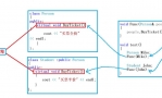
拓扑图:

实验要求及步骤:
1.根据图中的IP地址,合理规划各设备接口和PC的IP地址; 2.校园网按照图示划分VLAN,各VLAN通过三层交换机SVI实现通信;另外三层交换机F0/24口开启三层功能并配置IP地址。 3.在网络设备SW1,R3上配置静态路由,在R2上配置默认路由,实现各网段的连通; 4.给各路由器配置主机名,如图所示; 5.在路由器R3上配置loopback接口,配置IP地址为3.3.3.3/24,将其作为路由器远程登录的地址,并进行远程登录 的相关配置,实现路由器R3能够远程登录; 6.在server上配置WWW服务,使得远程主机可以访问WWW。
***********************规划IP地址*****************************

******************划分VLAN ,实现各VLAN通信******************** SW21 1
2
3
4
5
6
7
8
9
10
11
12
13
14
| Switch>enable
Switch#
Switch#conf t
Switch(config)#vlan 10 //创建vlan 10
Switch(config-vlan)#exit
Switch(config)#inter f 0/1
Switch(config-if)#switchport access vlan 10
Switch(config-if)#no shut
Switch(config-if)#exit
Switch(config)#inter f 0/23
//因为此线路要实现VLAN包的转发,所以要配置成trunk链路
Switch(config-if)#switchport mode trunk Switch(config-if)#no shut
Switch(config-if)#exit
Switch(config)#
|
SW 22 1
2
3
4
5
6
7
8
9
10
| Switch(config)#vlan 20
Switch(config-vlan)#exit
Switch(config)#
Switch(config)#inter f 0/1
Switch(config-if)#switchport access vlan 20
Switch(config-if)#no shut
Switch(config-if)#exit
Switch(config)#inter f 0/22
Switch(config-if)#switchport mode trunk
Switch(config-if)#no shut
|
SW23的配置同理与SW21和SW22 SW31 1
2
3
4
5
6
7
8
9
10
11
12
13
14
15
16
17
18
19
20
21
22
23
24
25
26
27
28
| Switch#conf t
Enter configuration commands, one per line. End with CNTL/Z.
Switch(config)#
Switch(config)#hostname SW31
SW31(config)#vlan 10
SW31(config-vlan)#exit
SW31(config)#vlan 20
SW31(config-vlan)#exit
SW31(config)#vlan 30
SW31(config-vlan)#exit //创建三个vlan的虚接口
SW31(config)#inter vlan 10
SW31(config-if)#ip address 192.168.10.254 255.255.255.0
SW31(config-if)#no shut
SW31(config-if)#exit
SW31(config)#inter vlan 20
SW31(config-if)#ip address 192.168.20.254 255.255.255.0
SW31(config-if)#no shut
SW31(config-if)#
SW31(config-if)#exit
SW31(config)#
SW31(config)#inter vlan 30
SW31(config-if)#ip address 192.168.30.254 255.255.255.0
SW31(config-if)#no shut
SW31(config-if)#exit //配置所有vlan的IP地址
SW31(config)#
//开启三层交换机路由功能,实现不同VLAN之间的通信以及路由功能
SW31(config)#ip routing
SW31(config)#
|
Vlan 10 ping vlan 20 其他各vlan 一样能ping通
*********************给各路由器端口配置IP地址********************
1
2
3
4
5
6
7
| SW31(config)#inter f 0/24
SW31(config-if)#no switchport
SW31(config-if)#ip ad
SW31(config-if)#ip address 192.168.40.1 255.255.255.0
SW31(config-if)#no shut
SW31(config-if)#exit
SW31(config)#
|
1
2
3
4
5
6
7
8
9
| Router(config)#hostname R3
R3(config)#inter f0/0
R3(config-if)#ip address 192.168.40.2 255.255.255.0
R3(config-if)#no shut
R3(config-if)#exit
R3(config)#inter s 0/1/1
R3(config-if)#ip ad
R3(config-if)#ip address 23.0.0.1 255.255.255.0
R3(config-if)#no shut
|
1
2
3
4
5
6
7
8
9
10
11
| Router(config)#hostname R2
R2(config)#inter s 0/1/1
R2(config-if)#clock rate 64000
R2(config-if)#ip address 23.0.0.2 255.255.255.0
R2(config-if)#no shut
R2(config-if)#exit
R2(config)#
R2(config)#inter f 0/0
R2(config-if)#ip add
R2(config-if)#ip address 200.0.0.254 255.255.255.0
R2(config-if)#no shut
|
*******配置各个路由器的静态路由与R2的默认路由,实现全网段连通****
1
2
3
4
5
6
7
8
9
10
11
12
| R3(config)#ip route 192.168.10.0 255.255.255.0 192.168.40.1
R3(config)#ip route 192.168.20.0 255.255.255.0 192.168.40.1
R3(config)#ip route 192.168.30.0 255.255.255.0 192.168.40.1
R3#show ip route
..........................
..........................
C 23.0.0.0 is directly connected, Serial0/1/1
S 192.168.10.0/24 [1/0] via 192.168.40.1
S 192.168.20.0/24 [1/0] via 192.168.40.1
S 192.168.30.0/24 [1/0] via 192.168.40.1
C 192.168.40.0/24 is directly connected, FastEthernet0/0
|
此时各个vlan中的PC机都能ping通R3的F0/0接口
1
2
3
4
5
6
7
8
9
10
| SW31(config)#ip route 23.0.0.0 255.255.255.0 192.168.40.2
SW31(config)#exit
SW31#show ip route
.........................................
S 23.0.0.0 [1/0] via 192.168.40.2
C 192.168.10.0/24 is directly connected, Vlan10
C 192.168.20.0/24 is directly connected, Vlan20
C 192.168.30.0/24 is directly connected, Vlan30
C 192.168.40.0/24 is directly connected, FastEthernet0/24
|
此时,各vlan中的所有PC机都能ping通R3的S 0/1/1接口
1
2
3
4
5
6
7
8
9
10
11
12
| R2(config)#ip route 192.168.10.0 255.255.255.0 23.0.0.1
R2(config)#ip route 192.168.20.0 255.255.255.0 23.0.0.1
R2(config)#ip route 192.168.30.0 255.255.255.0 23.0.0.1
R2(config)#exit
R2#
R2#show ip route
..........................................
C 23.0.0.0 is directly connected, Serial0/1/1
S 192.168.10.0/24 [1/0] via 23.0.0.1
S 192.168.20.0/24 [1/0] via 23.0.0.1
S 192.168.30.0/24 [1/0] via 23.0.0.1
C 200.0.0.0/24 is directly connected, FastEthernet0/0
|
此时,各vlan中的所有PC机都能ping通R2的s 0/1/1接口 但是题目中要求要在R2是配置的是默认路由,所以在R2上 1
2
3
4
5
6
7
8
9
10
11
12
13
| R2(config)#no ip route 192.168.10.0 255.255.255.0 23.0.0.1
R2(config)#no ip route 192.168.20.0 255.255.255.0 23.0.0.1
R2(config)#no ip route 192.168.30.0 255.255.255.0 23.0.0.1 //删除静态路由
R2(config)#ip route 0.0.0.0 255.255.255.0 23.0.0.1 //添加默认路由
R2(config)#exit
R2#show ip route
..........................................
* 0.0.0.0/24 is subnetted, 1 subnets
S* 0.0.0.0 [1/0] via 23.0.0.1
23.0.0.0/24 is subnetted, 1 subnets
C 23.0.0.0 is directly connected, Serial0/1/1
C 200.0.0.0/24 is directly connected, FastEthernet0/0
|
此时各vlan中的PC机依然能ping 通R2的s 0/1/1接口

1
2
3
4
5
6
7
8
9
| SW31(config)#ip route 200.0.0.0 255.255.255.0 192.168.40.2
SW31#show ip route
......................................................
S 23.0.0.0 [1/0] via 192.168.40.2
C 192.168.10.0/24 is directly connected, Vlan10
C 192.168.20.0/24 is directly connected, Vlan20
C 192.168.30.0/24 is directly connected, Vlan30
C 192.168.40.0/24 is directly connected, FastEthernet0/24
S 200.0.0.0/24 [1/0] via 192.168.40.2
|
1
2
3
4
5
6
7
8
9
10
11
12
13
| R3(config)#ip route 200.0.0.0 255.255.255.0 23.0.0.2
R3(config)#exit
R3#
R3#
R3#show ip route
....................................................
C 23.0.0.0 is directly connected, Serial0/1/1
S 192.168.10.0/24 [1/0] via 192.168.40.1
S 192.168.20.0/24 [1/0] via 192.168.40.1
S 192.168.30.0/24 [1/0] via 192.168.40.1
C 192.168.40.0/24 is directly connected, FastEthernet0/0
S 200.0.0.0/24 [1/0] via 23.0.0.2
|
此时各vlan所有PC机都能ping通R2的f 0/0接口 而且所有pC机都能访问WEB服务器


*********在路由器上配置loopback 0接口,并配置静态路由,使其连通*** 1
2
3
4
5
| R3(config)#inter loopback 0
R3(config-if)#ip add
R3(config-if)#ip address 3.3.3.3 255.255.255.0
R3(config-if)#no shut
R3(config-if)#exit
|
1
2
3
4
5
6
7
8
9
10
11
12
13
14
15
16
| SW31(config)#ip route 3.3.3.0 255.255.255.0 192.168.40.2
SW31(config)#exit
SW31#
%SYS-5-CONFIG_I: Configured from console by console
SW31#show ip route
...................................................
3.0.0.0/24 is subnetted, 1 subnets
S 3.3.3.0 [1/0] via 192.168.40.2
23.0.0.0/24 is subnetted, 1 subnets
S 23.0.0.0 [1/0] via 192.168.40.2
C 192.168.10.0/24 is directly connected, Vlan10
C 192.168.20.0/24 is directly connected, Vlan20
C 192.168.30.0/24 is directly connected, Vlan30
C 192.168.40.0/24 is directly connected, FastEthernet0/24
S 200.0.0.0/24 [1/0] via 192.168.40.2
|
此时各vlanPC机能ping通 3.3.3.0网络 ********将loopbace 0作为路由器远程登录地址,并进行远程登录***** 1
2
3
4
5
6
7
| R3(config)#enable password 123456
R3(config)#login
R3(config)#line vty 0 4
R3(config-line)#pas
R3(config-line)#password 123
R3(config-line)#login
R3(config-line)#
|
此时各vlan中所有PC机都能通过远程telnet登录到3.3.3.3上

|  QQ群⑧:
QQ群⑧:


 窥视卡
窥视卡 雷达卡
雷达卡 发表于 2014-11-28 09:07:09


 提升卡
提升卡 置顶卡
置顶卡 沉默卡
沉默卡 喧嚣卡
喧嚣卡 变色卡
变色卡 千斤顶
千斤顶 显身卡
显身卡