1.LDP协议的各种情况
2.LDP和BGP交互
3.LDP高级部分
4.MPLS VPN (RIP和静态)
5.MPLS VPN (EIGRP)
6.MPLS VPN (OSPF)
7.MPLS VPN (EBGP)
8.Overlapping VPN和Central Service VPN
9.MPLS VPN (Internet Access)
10.组播VPN (mVPN)
11.Inter AS MPLS VPN (Option A)
12.Inter AS MPLS VPN (Option B)
13.Inter AS MPLS VPN (Option C)
14.CSC - Carrier Support Carrier
15.6vPE
16.MPLS TE各种情况
17.PMLS TE FRR
enable
conf t
no ip do lo
enable pass cisco
line con 0
logg sync
exec-t 0 0
line vty 0 4
pass cisco
logg sync
exit
host
1.LDP协议的各种情况
------------------------------------------------------------------------------------
实验目的:
1).掌握LDP router-id的选取原则和更改LDP router-id的方法
2).掌握测试LSP通道的方法,观察LSP标签通道
3).掌握LDP标签分配范围的指定方法
4).掌握LDP的认证方法
5).掌握对LDP标签的控制发送
6).掌握对LDP标签的控制接收
7).理解并修改MPLS MTU
配置接口IP和OSPF
R1:
int f1/0
ip add 13.1.1.1 255.255.255.0
no shut
exit
int l0
ip add 11.1.1.1 255.255.255.255
no shut
exit
router ospf 1
router-id 11.1.1.1
network 11.1.1.1 0.0.0.0 area 0
network 13.1.1.0 0.0.0.255 area 0
exit
R3:
int f1/0
ip add 13.1.1.3 255.255.255.0
no shut
exit
int p2/0
ip add 35.1.1.3 255.255.255.0
no shut
exit
int l0
ip add 33.1.1.1 255.255.255.255
no shut
exit
router ospf 1
router-id 33.1.1.1
network 33.1.1.1 0.0.0.0 area 0
network 13.1.1.0 0.0.0.255 area 0
network 35.1.1.0 0.0.0.255 area 0
exit
R5:
int p2/0
ip add 35.1.1.5 255.255.255.0
no shut
exit
int f1/0
ip add 58.1.1.5 255.255.255.0
no shut
exit
int l0
ip add 55.1.1.1 255.255.255.255
no shut
exit
router ospf 1
router-id 55.1.1.1
network 55.1.1.1 0.0.0.0 area 0
network 35.1.1.0 0.0.0.255 area 0
network 58.1.1.0 0.0.0.255 area 0
exit
R8:
int f1/0
ip add 58.1.1.8 255.255.255.0
no shut
exit
int l0
ip add 88.1.1.1 255.255.255.255
no shut
exit
router ospf 1
router-id 88.1.1.1
network 88.1.1.1 0.0.0.0 area 0
network 58.1.1.0 0.0.0.255 area 0
exit
View Code 配置MPLS LDP
R1:
int l1
ip add 100.1.1.1 255.255.255.255
exit
ip cef
mpls ip
mpls label protocol ldp
mpls label range 100 199
no mpls label range 100 199
int f1/0
mpls ip
exit
show mpls ldp discovery
路由器自动选择的LDP router-id为R1上最大的loopback1接口IP.
mpls ldp router-id l0 force
show mpls ldp discovery
路由器选择的LDP router-id为R1上最大的loopback0接口IP,注意一定要加上force参数
R3:
int f1/0
mpls ip
exit
int p2/0
mpls ip
exit
R5:
int f1/0
mpls ip
exit
int p2/0
mpls ip
exit
R8:
int f1/0
mpls ip
exit
R3:
show mpls ldp neighbor
邻居关系是利用TCP连接形成的,该TCP连接的IP地址为LDP的transport address,缺省为LDP 的router-id。如果router-id之间没有路由,可以用直连接口IP地址建立邻居关系,其实就是更改transport address为直连接口IP地址,修改命令为接口下,mpls ldp discovery transport-add interface.
R1:
ping 88.1.1.1
ping mpls ipv4 88.1.1.1/32
测试确定LSP的通道已经形成。
R5:
int f1/0
no mpls ip
exit
R1:
ping mpls ipv4 88.1.1.1/32
返回的表示BBBBB表示LSP通道在某处中断。
R5:
int f1/0
mpls ip
exit
R1:
traceroute mpls ipv4 88.1.1.1/32
R1/R3/R5/R8:
show mpls forwarding-table
R5:
mpls label range 500 599
show mpls forwarding-table
存盘并重启R5(采用dynamips进行模拟,需要到dynamips界面下进行重启)
show mpls forwarding-table
R5:
mpls ldp neighbor 33.1.1.1 password yeslab
R3:
mpls ldp neighbor 55.1.1.1 password yeslab
配置邻居认证时,要指定邻居的LDP router-id
R5:
no mpls ldp advertise-lables
access-list 1 permit 33.1.1.1
access-list 2 permit 58.1.1.0
mpls ldp advertise-lables for 2 to 1
R3:
show mpls forwarding-table
R8:
show mpls forwarding-table
R5上配置的no mpls ldp advertise-label影响了给所有的LDP邻居传递标签。
R5:
access-list 3 deny 33.1.1.1
access-list 3 permit any
access-list 4 permit any
mpls ldp advertise-labels for 4 to 3
R8:
show mpls forwarding-table
access-list 1 permit 11.1.1.1
access-list 1 permit 33.1.1.1
access-list 1 permit 55.1.1.1
mpls ldp neighbor 55.1.1.1 labels accept 1
show mpls forwarding-table
R8只接收了指定前缀的标签
R5:
mpls ldp advertise-lables
no access-list 1
no access-list 2
no access-list 3
no access-list 4
R8:
no access-list 1
no mpls ldp neighbor 55.1.1.1 labels accept 1
承载MPLS包时,IP MTU为1500-N*4(N为标签个数),导致数据包在MPLS接口被分片。有必要调整全网MPLS MTU以避免这种情况。缺省情况下,MPLS MTU等于出接口的MTU。
R1:
show ip int f1/0
show mpls int f1/0 detail
R3:
show ip int p2/0
show mpls int p2/0 detail
R1:
ping 88.1.1.1 size 1800
在R1的F1/0接口和R3的P2/0接口抓包观察包分片情况。接口分片的时候,是先执行分片,然后加上MPLS标签再传出去。
ping 88.1.1.1 df-bit size 1496
ping 88.1.1.1 df-bit size 1497
int f1/0
mtu 1504
exit
show mpls int f1/0 detail
R5:
int f1/0
mpls mtu override 1504
exit
show mpls int f1/0 detail
R1:
ping 88.1.1.1 df-bit size 1500
R8:
int f1/0
mpls mtu override 1504
exit
R3:
int f1/0
mtu 1504
exit
R1:
ping 88.1.1.1 df-bit size 1500
View Code
2.LDP和BGP交互
-------------------------------------------------------------------------------------
实验目的:
1).掌握LDP不为BGP前缀分配标签,而是为BGP前缀的next-hop分配标签
2).掌握通过标签交互,可以消除路由黑洞
传统的路由转发方式,要求经过的每一跳路由器都有对应的路由,否则将数据包丢弃。因此需要建立全互联的BGP对等体,或者路由反射器,以将路由同步到整个网络。在MPLS网络里,使用标签交互的方式,可以在中间路由器没有对应路由的情况下,利用标签交互,将数据报文送达目的地。
R3:
router bgp 100
bgp router-id 33.1.1.1
neighbor 88.1.1.1 remote-as 100
neighbor 88.1.1.1 update-source l0
exit
R8:
router bgp 100
bgp router-id 88.1.1.1
neighbor 33.1.1.1 remote-as 100
neighbor 33.1.1.1 update-source l0
exit
int l1
ip add 188.1.1.1 255.255.255.0
exit
router bgp 100
network 188.1.1.0 mask 255.255.255.0
exit
R3/R5:
show ip route
R5没有188.1.1.0、24这条路由,相当于路由黑洞。
R1:
ip route 0.0.0.0 0.0.0.0 13.1.1.3
int f1/0
no mpls ip
exit
R3:
int f1/0
no mpls ip
exit
R3/R5/R8:
mpls ldp router-id l0 force
R1:
ping 188.1.1.1
traceroute 188.1.1.1
R3/R5:
show mpls forwarding-table
View Code 当数据包从IP域进入MPLS域的时候,如果依据BGP条目转发数据包,打上标签值为BGP条目下一跳路由的标签,这样可以带来几个好处:1)标签转发表变小;2)不需要全网运行BGP并避免路由黑洞,减轻核心路由器的压力
R1:
int f1/0
ip add 13.1.1.1 255.255.255.0
no shut
exit
int l0
ip add 11.1.1.1 255.255.255.255
exit
router ospf 1
router-id 11.1.1.1
network 11.1.1.1 0.0.0.0 area 0
network 13.1.1.0 0.0.0.255 area 0
exit
R3:
int f1/0
ip add 13.1.1.3 255.255.255.0
no shut
exit
int f1/1
ip add 34.1.1.3 255.255.255.0
no shut
exit
int p2/0
ip add 35.1.1.3 255.255.255.0
no shut
exit
int l0
ip add 33.1.1.1 255.255.255.255
exit
router ospf 1
router-id 33.1.1.1
network 33.1.1.1 0.0.0.0 area 0
network 13.1.1.0 0.0.0.255 area 0
network 34.1.1.0 0.0.0.255 area 0
network 35.1.1.0 0.0.0.255 area 0
exit
R4:
int f1/1
ip add 34.1.1.4 255.255.255.0
no shut
exit
int p3/0
ip add 45.1.1.4 255.255.255.0
no shut
exit
int l0
ip add 44.1.1.1 255.255.255.255
exit
router ospf 1
router-id 44.1.1.1
network 33.1.1.1 0.0.0.0 area 0
network 34.1.1.0 0.0.0.255 area 0
network 45.1.1.0 0.0.0.255 area 0
exit
R5:
int p2/0
ip add 35.1.1.5 255.255.255.0
no shut
exit
int p3/0
ip add 45.1.1.5 255.255.255.0
no shut
exit
int f1/0
ip add 58.1.1.5 255.255.255.0
no shut
exit
int l0
ip add 55.1.1.1 255.255.255.255
exit
router ospf 1
router-id 55.1.1.1
network 55.1.1.1 0.0.0.0 area 0
network 35.1.1.0 0.0.0.255 area 0
network 45.1.1.0 0.0.0.255 area 0
network 58.1.1.0 0.0.0.255 area 0
exit
R8:
int f1/0
ip add 58.1.1.8 255.255.255.0
no shut
exit
int l0
ip add 88.1.1.1 255.255.255.255
no shut
exit
router ospf 1
router-id 88.1.1.1
network 88.1.1.1 0.0.0.0 area 0
network 58.1.1.0 0.0.0.255 area 0
exit
View Code
4.MPLS VPN (RIP和静态)
-------------------------------------------------------------------------------------
实验目的:
1).掌握MPLS VPN的配置步骤
2).在PE和CE之间运行RIP和静态路由的情况下,观察CE路由的传递
3).掌握MPLS VPN数据包在传递过程中如何查询各种表
1).基本配置
2).配置接口IP以及ISP网络的IGP(OSPF)
3).ISP网络使能LDP协议
4).ISP网络建立MP-BGP邻居关系
5).PE设备创建vrf
6).PE与CE间路由配置(RIP和静态)
7).vrf路由协议与MP-BGP之间相互重分布
1).基本配置
-----------------------------------------------------------
enable
conf t
no ip do lo
enable pass cisco
line con 0
logg sync
exec-t 0 0
line vty 0 4
pass cisco
logg sync
exit
host
2).配置接口IP以及ISP网络的IGP(OSPF)
R2:
int l0
ip add 22.1.1.1 255.255.255.255
no shut
exit
int g4/0
ip add 23.1.1.2 255.255.255.0
no shut
exit
int f0/0
ip add 24.1.1.2 255.255.255.0
no shut
exit
R3:
int l0
ip add 33.1.1.1 255.255.255.255
no shut
exit
int g4/0
ip add 23.1.1.3 255.255.255.0
no shut
exit
int p2/0
ip add 35.1.1.3 255.255.255.0
no shut
exit
router ospf 1
router-id 33.1.1.1
network 33.1.1.1 0.0.0.0 area 0
network 35.1.1.0 0.0.0.255 area 0
exit
R4:
int l0
ip add 44.1.1.1 255.255.255.255
no shut
exit
int f0/0
ip add 24.1.1.4 255.255.255.0
no shut
exit
int p3/0
ip add 45.1.1.4 255.255.255.0
no shut
exit
int g4/0
ip add 46.1.1.4 255.255.255.0
no shut
exit
router ospf 1
router-id 44.1.1.1
network 44.1.1.1 0.0.0.0 area 0
network 45.1.1.0 0.0.0.255 area 0
network 46.1.1.0 0.0.0.255 area 0
exit
R5:
int l0
ip add 55.1.1.1 255.255.255.255
no shut
exit
int f1/0
ip add 58.1.1.5 255.255.255.0
no shut
exit
int p3/0
ip add 45.1.1.5 255.255.255.0
no shut
exit
int p2/0
ip add 35.1.1.5 255.255.255.0
no shut
exit
router ospf 1
router-id 55.1.1.1
network 55.1.1.1 0.0.0.0 area 0
network 35.1.1.0 0.0.0.255 area 0
network 45.1.1.0 0.0.0.255 area 0
exit
R6:
int l0
ip add 66.1.1.1 255.255.255.255
no shut
exit
int f0/0
ip add 67.1.1.6 255.255.255.0
no shut
exit
int g4/0
ip add 46.1.1.6 255.255.255.0
no shut
exit
router ospf 1
router-id 66.1.1.1
network 66.1.1.1 0.0.0.0 area 0
network 46.1.1.0 0.0.0.255 area 0
exit
R7:
int l0
ip add 77.1.1.1 255.255.255.255
no shut
exit
int f0/0
ip add 67.1.1.7 255.255.255.0
no shut
exit
R8:
int l0
ip add 88.1.1.1 255.255.255.255
no shut
exit
int f1/0
ip add 58.1.1.8 255.255.255.0
no shut
exit
View Code 3).ISP网络使能LDP协议
R3:
mpls ldp router-id l0 force
int p2/0
mpls ip
exit
R4:
mpls ldp router-id l0 force
int p3/0
mpls ip
exit
int g4/0
mpls ip
exit
R5:
mpls ldp router-id l0 force
int p2/0
mpls ip
exit
int p3/0
mpls ip
exit
R6:
mpls ldp router-id l0 force
int g4/0
mpls ip
exit
View Code 4).ISP网络建立MP-BGP邻居关系
1).基本配置
2).配置接口IP以及ISP网络的IGP(OSPF)
3).ISP网络使能LDP协议
4).ISP网络建立MP-BGP邻居关系
5).PE设备创建vrf
6).PE与CE间路由配置(RIP和静态)
7).vrf路由协议与MP-BGP之间相互重分布
1).基本配置
-----------------------------------------------------------
enable
conf t
no ip do lo
enable pass cisco
line con 0
logg sync
exec-t 0 0
line vty 0 4
pass cisco
logg sync
exit
host
2).配置接口IP以及ISP网络的IGP(OSPF)
R2:
int l0
ip add 22.1.1.1 255.255.255.255
no shut
exit
int g4/0
ip add 23.1.1.2 255.255.255.0
no shut
exit
int f0/0
ip add 24.1.1.2 255.255.255.0
no shut
exit
R3:
int l0
ip add 33.1.1.1 255.255.255.255
no shut
exit
int g4/0
ip add 23.1.1.3 255.255.255.0
no shut
exit
int p2/0
ip add 35.1.1.3 255.255.255.0
no shut
exit
router eigrp 100
no auto-summary
network 33.1.1.1 0.0.0.0
network 35.1.1.3 0.0.0.0
exit
R4:
int l0
ip add 44.1.1.1 255.255.255.255
no shut
exit
int f0/0
ip add 24.1.1.4 255.255.255.0
no shut
exit
int p3/0
ip add 45.1.1.4 255.255.255.0
no shut
exit
int g4/0
ip add 46.1.1.4 255.255.255.0
no shut
exit
router eigrp 100
no auto-summary
network 44.1.1.1 0.0.0.0
network 45.1.1.4 0.0.0.0
network 46.1.1.4 0.0.0.0
exit
R5:
int l0
ip add 55.1.1.1 255.255.255.255
no shut
exit
int f1/0
ip add 58.1.1.5 255.255.255.0
no shut
exit
int p3/0
ip add 45.1.1.5 255.255.255.0
no shut
exit
int p2/0
ip add 35.1.1.5 255.255.255.0
no shut
exit
router eigrp 100
no auto-summary
network 55.1.1.1 0.0.0.0
network 35.1.1.5 0.0.0.0
network 45.1.1.5 0.0.0.0
exit
R6:
int l0
ip add 66.1.1.1 255.255.255.255
no shut
exit
int f0/0
ip add 67.1.1.6 255.255.255.0
no shut
exit
int g4/0
ip add 46.1.1.6 255.255.255.0
no shut
exit
router eigrp 100
no auto-summary
network 66.1.1.1 0.0.0.0
network 46.1.1.6 0.0.0.0
exit
R7:
int l0
ip add 77.1.1.1 255.255.255.255
no shut
exit
int f0/0
ip add 67.1.1.7 255.255.255.0
no shut
exit
R8:
int l0
ip add 88.1.1.1 255.255.255.255
no shut
exit
int f1/0
ip add 58.1.1.8 255.255.255.0
no shut
exit
View Code 3).ISP网络使能LDP协议
R3:
mpls ldp router-id l0 force
int p2/0
mpls ip
exit
R4:
mpls ldp router-id l0 force
int p3/0
mpls ip
exit
int g4/0
mpls ip
exit
R5:
mpls ldp router-id l0 force
int p2/0
mpls ip
exit
int p3/0
mpls ip
exit
R6:
mpls ldp router-id l0 force
int g4/0
mpls ip
exit
View Code 4).ISP网络建立MP-BGP邻居关系
R5:
route-map soo
set extcommunity soo 100:5678
exit
int f1/0
ip vrf sitemap soo
exit
R6:
route-map soo
set extcommunity soo 100:5678
exit
int f0/0
ip vrf sitemap soo
exit
R6:
show ip bgp vpnv4 all 88.1.1.1
R7:
show ip route
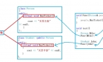
View Code SoO的防环机制,是在PE传递路由给CE的时候,检查出接口配置的SoO值是否与从其他MP-BGP邻居收到的VPNv4路由的SoO值一致,如果一致,就不传给CE。
6.MPLS VPN (OSPF)
--------------------------------------------------------------------------------------
实验目的:
1).掌握MPLS VPN的配置步骤
2).掌握在PE和CE之间运行OSPF情况下的配置
3).观察domain-id的配置和作用
4).观察CE路由的传递过程附加的OSPF相关的community值
5).掌握PE和CE站点运行OSPF情况下的防环机制
6).掌握sham-link的配置和作用
1).基本配置
2).配置接口IP以及ISP网络的IGP(OSPF)
3).ISP网络使能LDP协议
4).ISP网络建立MP-BGP邻居关系
5).PE设备创建vrf
6).PE与CE间路由配置(RIP和静态)
7).vrf路由协议与MP-BGP之间相互重分布
1).基本配置
-----------------------------------------------------------
enable
conf t
no ip do lo
enable pass cisco
line con 0
logg sync
exec-t 0 0
line vty 0 4
pass cisco
logg sync
exit
host
2).配置接口IP以及ISP网络的IGP(OSPF)
R2:
int l0
ip add 22.1.1.1 255.255.255.255
no shut
exit
int g4/0
ip add 23.1.1.2 255.255.255.0
no shut
exit
int f0/0
ip add 24.1.1.2 255.255.255.0
no shut
exit
R3:
int l0
ip add 33.1.1.1 255.255.255.255
no shut
exit
int g4/0
ip add 23.1.1.3 255.255.255.0
no shut
exit
int p2/0
ip add 35.1.1.3 255.255.255.0
no shut
exit
router ospf 1
router-id 33.1.1.1
network 33.1.1.1 0.0.0.0 area 0
network 35.1.1.0 0.0.0.255 area 0
exit
R4:
int l0
ip add 44.1.1.1 255.255.255.255
no shut
exit
int f0/0
ip add 24.1.1.4 255.255.255.0
no shut
exit
int p3/0
ip add 45.1.1.4 255.255.255.0
no shut
exit
int g4/0
ip add 46.1.1.4 255.255.255.0
no shut
exit
router ospf 1
router-id 44.1.1.1
network 44.1.1.1 0.0.0.0 area 0
network 45.1.1.0 0.0.0.255 area 0
network 46.1.1.0 0.0.0.255 area 0
exit
R5:
int l0
ip add 55.1.1.1 255.255.255.255
no shut
exit
int f1/0
ip add 58.1.1.5 255.255.255.0
no shut
exit
int p3/0
ip add 45.1.1.5 255.255.255.0
no shut
exit
int p2/0
ip add 35.1.1.5 255.255.255.0
no shut
exit
router ospf 1
router-id 55.1.1.1
network 55.1.1.1 0.0.0.0 area 0
network 35.1.1.0 0.0.0.255 area 0
network 45.1.1.0 0.0.0.255 area 0
exit
R6:
int l0
ip add 66.1.1.1 255.255.255.255
no shut
exit
int f0/0
ip add 67.1.1.6 255.255.255.0
no shut
exit
int g4/0
ip add 46.1.1.6 255.255.255.0
no shut
exit
router ospf 1
router-id 66.1.1.1
network 66.1.1.1 0.0.0.0 area 0
network 46.1.1.0 0.0.0.255 area 0
exit
R7:
int l0
ip add 77.1.1.1 255.255.255.255
no shut
exit
int f0/0
ip add 67.1.1.7 255.255.255.0
no shut
exit
R8:
int l0
ip add 88.1.1.1 255.255.255.255
no shut
exit
int f1/0
ip add 58.1.1.8 255.255.255.0
no shut
exit
View Code 3).ISP网络使能LDP协议
R3:
mpls ldp router-id l0 force
int p2/0
mpls ip
exit
R4:
mpls ldp router-id l0 force
int p3/0
mpls ip
exit
int g4/0
mpls ip
exit
R5:
mpls ldp router-id l0 force
int p2/0
mpls ip
exit
int p3/0
mpls ip
exit
R6:
mpls ldp router-id l0 force
int g4/0
mpls ip
exit
View Code 4).ISP网络建立MP-BGP邻居关系
R7:
show ip route ospf
R6:
show ip bgp vpnv4 all 22.1.1.1
R3/R4:
router ospf 34
domain-id type 0005 value 000000380200
R7:
show ip route ospf
R8:
int l1
ip add 188.1.1.1 255.255.255.0
exit
router ospf 1
redistribute connected subnets
exit
R6:
show ip bgp vpnv4 all 188.1.1.0
OSPF在MPLS VPN环境的防环机制
对内部路由,采用的是down bit机制;对外部路由,采用的是tag机制
R7:
show ip ospf database summary 22.1.1.1
R2:
int l1
ip add 122.1.1.1 255.255.255.255
exit
router ospf 1
redistribute connected subnets
exit
R7:
show ip route 122.1.1.1
View Code 配置sham-link
R5:
int l1
ip vrf forwarding yeslab
ip add 155.1.1.1 255.255.255.255
exit
router bgp 100
address-family ipv4 vrf yeslab
network 155.1.1.1 mask 255.255.255.255
exit
R6:
int l1
ip vrf forwarding yeslab
ip add 166.1.1.1 255.255.255.255
exit
router bgp 100
address-family ipv4 vrf yeslab
network 166.1.1.1 mask 255.255.255.255
exit
R5:
router ospf 56 vrf yeslab
area 1 sham-link 155.1.1.1 166.1.1.1
exit
R6:
router ospf 56 vrf yeslab
area 1 sham-link 166.1.1.1 155.1.1.1
exit
R6:
show ip ospf sham-link
R7:
show ip route 88.1.1.1
int f1/1
ip ospf cost 10
exit
show ip route 88.1.1.1
View Code
7.MPLS VPN (EBGP)
----------------------------------------------------------------------------------------
实验目的:
1).掌握MPLS VPN的配置步骤
2).掌握在PE和CE之间运行EBGP情况下的配置
3).掌握allowas-in和as-override的配置场景和配置方法
4).掌握限制从CE学来BGP路由条目数的方法
1).基本配置
2).配置接口IP以及ISP网络的IGP(OSPF)
3).ISP网络使能LDP协议
4).ISP网络建立MP-BGP邻居关系
5).PE设备创建vrf
6).PE与CE间路由配置(EBGP)
1).基本配置
-----------------------------------------------------------
enable
conf t
no ip do lo
enable pass cisco
line con 0
logg sync
exec-t 0 0
line vty 0 4
pass cisco
logg sync
exit
host
2).配置接口IP以及ISP网络的IGP(OSPF)
R2:
int l0
ip add 22.1.1.1 255.255.255.255
no shut
exit
int g4/0
ip add 23.1.1.2 255.255.255.0
no shut
exit
int f0/0
ip add 24.1.1.2 255.255.255.0
no shut
exit
R3:
int l0
ip add 33.1.1.1 255.255.255.255
no shut
exit
int g4/0
ip add 23.1.1.3 255.255.255.0
no shut
exit
int p2/0
ip add 35.1.1.3 255.255.255.0
no shut
exit
router ospf 1
router-id 33.1.1.1
network 33.1.1.1 0.0.0.0 area 0
network 35.1.1.0 0.0.0.255 area 0
exit
R4:
int l0
ip add 44.1.1.1 255.255.255.255
no shut
exit
int f0/0
ip add 24.1.1.4 255.255.255.0
no shut
exit
int p3/0
ip add 45.1.1.4 255.255.255.0
no shut
exit
int g4/0
ip add 46.1.1.4 255.255.255.0
no shut
exit
router ospf 1
router-id 44.1.1.1
network 44.1.1.1 0.0.0.0 area 0
network 45.1.1.0 0.0.0.255 area 0
network 46.1.1.0 0.0.0.255 area 0
exit
R5:
int l0
ip add 55.1.1.1 255.255.255.255
no shut
exit
int f1/0
ip add 58.1.1.5 255.255.255.0
no shut
exit
int p3/0
ip add 45.1.1.5 255.255.255.0
no shut
exit
int p2/0
ip add 35.1.1.5 255.255.255.0
no shut
exit
router ospf 1
router-id 55.1.1.1
network 55.1.1.1 0.0.0.0 area 0
network 35.1.1.0 0.0.0.255 area 0
network 45.1.1.0 0.0.0.255 area 0
exit
R6:
int l0
ip add 66.1.1.1 255.255.255.255
no shut
exit
int f0/0
ip add 67.1.1.6 255.255.255.0
no shut
exit
int g4/0
ip add 46.1.1.6 255.255.255.0
no shut
exit
router ospf 1
router-id 66.1.1.1
network 66.1.1.1 0.0.0.0 area 0
network 46.1.1.0 0.0.0.255 area 0
exit
R7:
int l0
ip add 77.1.1.1 255.255.255.255
no shut
exit
int f0/0
ip add 67.1.1.7 255.255.255.0
no shut
exit
R8:
int l0
ip add 88.1.1.1 255.255.255.255
no shut
exit
int f1/0
ip add 58.1.1.8 255.255.255.0
no shut
exit
View Code 3).ISP网络使能LDP协议
R3:
mpls ldp router-id l0 force
int p2/0
mpls ip
exit
R4:
mpls ldp router-id l0 force
int p3/0
mpls ip
exit
int g4/0
mpls ip
exit
R5:
mpls ldp router-id l0 force
int p2/0
mpls ip
exit
int p3/0
mpls ip
exit
R6:
mpls ldp router-id l0 force
int g4/0
mpls ip
exit
View Code 4).ISP网络建立MP-BGP邻居关系
R1:
int f1/0
ip add 13.1.1.1 255.255.255.0
no shut
exit
int l0
ip add 11.1.1.1 255.255.255.255
exit
R2:
int f0/0
ip add 24.1.1.2 255.255.255.0
no shut
exit
int l0
ip add 22.1.1.1 255.255.255.255
exit
R3:
int f1/0
ip add 13.1.1.3 255.255.255.0
no shut
exit
int f1/1
ip add 34.1.1.3 255.255.255.0
no shut
exit
int p2/0
ip add 35.1.1.3 255.255.255.0
no shut
exit
int p3/0
ip add 36.1.1.3 255.255.255.0
no shut
exit
int l0
ip add 33.1.1.1 255.255.255.255
exit
router ospf 1
router-id 33.1.1.1
network 34.1.1.0 0.0.0.255 area 0
network 35.1.1.0 0.0.0.255 area 0
network 36.1.1.0 0.0.0.255 area 0
network 33.1.1.1 0.0.0.0 area 0
exit
R4:
int f0/0
ip add 24.1.1.4 255.255.255.0
no shut
exit
int f1/0
ip add 49.1.1.4 255.255.255.0
no shut
exit
int f1/1
ip add 34.1.1.4 255.255.255.0
no shut
exit
int g4/0
ip add 46.1.1.4 255.255.255.0
no shut
exit
int l0
ip add 44.1.1.1 255.255.255.255
exit
router ospf 1
router-id 44.1.1.1
network 34.1.1.0 0.0.0.255 area 0
network 46.1.1.0 0.0.0.255 area 0
network 44.1.1.1 0.0.0.0 area 0
exit
R5:
int f1/0
ip add 58.1.1.5 255.255.255.0
no shut
exit
int p2/0
ip add 35.1.1.5 255.255.255.0
no shut
exit
int l0
ip add 55.1.1.1 255.255.255.255
exit
router ospf 1
router-id 55.1.1.1
network 35.1.1.0 0.0.0.255 area 0
network 55.1.1.1 0.0.0.0 area 0
exit
R6:
int f0/0
ip add 67.1.1.6 255.255.255.0
no shut
exit
int f1/0
ip add 160.1.1.6 255.255.255.0
no shut
exit
int p3/0
ip add 36.1.1.6 255.255.255.0
no shut
exit
int g4/0
ip add 46.1.1.6 255.255.255.0
no shut
exit
int l0
ip add 66.1.1.1 255.255.255.255
exit
router ospf 1
router-id 66.1.1.1
network 36.1.1.0 0.0.0.255 area 0
network 46.1.1.0 0.0.0.255 area 0
network 66.1.1.1 0.0.0.0 area 0
R7:
int f0/0
ip add 67.1.1.7 255.255.255.0
no shut
exit
int l0
ip add 77.1.1.1 255.255.255.255
exit
R8:
int f1/0
ip add 58.1.1.8 255.255.255.0
no shut
exit
int l0
ip add 88.1.1.1 255.255.255.255
exit
R9:
int f1/0
ip add 49.1.1.9 255.255.255.0
no shut
exit
int l0
ip add 99.1.1.1 255.255.255.255
exit
R10:
int f1/0
ip add 160.1.1.10 255.255.255.0
no shut
exit
int l0
ip add 110.1.1.1 255.255.255.255
exit
View Code 2).ISP网络使能LDP协议
R3:
mpls ldp router-id l0 force
int p2/0
mpls ip
exit
int p3/0
mpls ip
exit
int f1/1
mpls ip
exit
R4:
mpls ldp router-id l0 force
int f1/1
mpls ip
exit
int g4/0
mpls ip
exit
R5:
mpls ldp router-id l0 force
int p2/0
mpls ip
exit
R6:
mpls ldp router-id l0 force
int g4/0
mpls ip
exit
int p3/0
mpls ip
exit
View Code 3).ISP网络建立MP-BGP邻居关系
R5:
int f1/0
no ip vrf forwarding yeslab2
exit
int f1/0.10
encapsulation dot1q 10
ip vrf forwarding yeslab2
ip add 58.1.1.5 255.255.255.0
exit
int f1/0.20
encapsulation dot1q 20
ip add 158.1.1.5 255.255.255.0
exit
R8:
int f1/0
no ip add
exit
int f1/0.10
encapsulation dot1q 10
ip add 58.1.1.8 255.255.255.0
exit
int f1/0.20
encapsulation dot1q 20
ip add 158.1.1.8 255.255.255.0
exit
ip route 0.0.0.0 0.0.0.0 158.1.1.5
R5:
access-list 1 permit 88.1.1.1
access-list 1 permit 158.1.1.0 0.0.0.255
access-list 1 permit 58.1.1.0 0.0.0.255
ip nat inside source list 1 int p2/0 overload
int p2/0
ip nat outside
exit
int f1/0.20
ip nat inside
exit
R8:
ping 44.1.1.1
R5:
show ip nat translation
View Code 配置任务:
1).CE R1站点访问internet,采用的是同一链路访问internet
2).配置CE R2、R7、R9、R10访问internet的流量都通过R1
3).对以上两步提到的CE流量,通过PE R3的时候,做NAT转换,转换为公网地址
R1:
router ospf 1
default-information originate always
exit
R3:
router bgp 100
address-family ipv4 vrf yeslab1
default-information originate
exit
R4:
router ospf 24 vrf yeslab1
default-information originate
exit
router ospf 49 vrf yeslab2
default-information originate
exit
R6:
router ospf 67 vrf yeslab1
default-information originate
exit
router ospf 610 vrf yeslab2
default-information originate
exit
注意:
在PE和CE之间运行OSPF协议的情况下,从一个CE往其他CE注入一条缺省路由的方法比较麻烦,具体配置如上。在CE和PE之间运行EBGP的情况下,注入方法简单,只需要在CE上配置基于PE的EBGP邻居发送缺省路由即可,这条缺省路由就会送到其他各个CE。
R1:
ip route 0.0.0.0 128.0.0.0 13.1.1.3
ip route 128.0.0.0 128.0.0.0 13.1.1.3
R3:
access-list 1 permit 22.1.1.1
access-list 1 permit 77.1.1.1
access-list 1 permit 99.1.1.1
access-list 1 permit 110.1.1.1
int f1/0
ip nat inside
exit
int f1/1
ip nat outside
ip nat inside source list 1 int f1/1 vrf yeslab1 overload
R3:
ip route 0.0.0.0 128.0.0.0 34.1.1.4 global
ip route 128.0.0.0 128.0.0.0 34.1.1.4 global
R1:
ping 44.1.1.1 source l0
R9/R10:
ping 55.1.1.1 source l0
R3:
show ip nat translations
R10:
traceroute 44.1.1.1 source l0
View Code
10.组播VPN (mVPN)
实验目的:
1).掌握mVPN的配置步骤
2).深入理解mVPN的工作过程和原理
3).深入理解ISP的各项组播路由表项
4).理解vpn的组播流如何穿越ISP网络
5).掌握default mdt向data mdt切换的配置方法
R2:
int l0
ip add 22.1.1.1 255.255.255.255
exit
int f1/0
ip add 29.1.1.2 255.255.255.0
no shutdown
exit
int g4/0
ip add 23.1.1.2 255.255.255.0
no shutdown
exit
int f0/0
ip add 24.1.1.2 255.255.255.0
no shutdown
exit
mpls ldp router-id l0 force
int l0
ip ospf 1 area 0
exit
int f0/0
ip ospf 1 area 0
mpls ip
exit
int g4/0
ip ospf 1 area 0
mpls ip
exit
router bgp 100
bgp router-id 22.1.1.1
no bgp default ipv4-unicast
neighbor 33.1.1.1 remote-as 100
neighbor 33.1.1.1 update-source l0
neighbor 44.1.1.1 remote-as 100
neighbor 44.1.1.1 update-source l0
neighbor 55.1.1.1 remote-as 100
neighbor 55.1.1.1 update-source l0
neighbor 66.1.1.1 remote-as 100
neighbor 66.1.1.1 update-source l0
address-family vpnv4 unicast
neighbor 33.1.1.1 activate
neighbor 44.1.1.1 activate
neighbor 55.1.1.1 activate
neighbor 66.1.1.1 activate
exit-address-family
exit
R3:
int l0
ip add 33.1.1.1 255.255.255.255
exit
int g4/0
ip add 23.1.1.3 255.255.255.0
no shutdown
exit
int f1/1
ip add 34.1.1.3 255.255.255.0
no shutdown
exit
int p2/0
ip add 35.1.1.3 255.255.255.0
no shutdown
exit
mpls ldp router-id l0 force
int l0
ip ospf 1 area 0
exit
int g4/0
ip ospf 1 area 0
mpls ip
exit
int f1/1
ip ospf 1 area 0
mpls ip
exit
int p2/0
ip ospf 1 area 0
mpls ip
exit
router bgp 100
bgp router-id 33.1.1.1
no bgp default ipv4-unicast
neighbor 22.1.1.1 remote-as 100
neighbor 22.1.1.1 update-source l0
neighbor 44.1.1.1 remote-as 100
neighbor 44.1.1.1 update-source l0
neighbor 55.1.1.1 remote-as 100
neighbor 55.1.1.1 update-source l0
neighbor 66.1.1.1 remote-as 100
neighbor 66.1.1.1 update-source l0
address-family vpnv4 unicast
neighbor 22.1.1.1 activate
neighbor 44.1.1.1 activate
neighbor 55.1.1.1 activate
neighbor 66.1.1.1 activate
exit-address-family
exit
R4:
int l0
ip add 44.1.1.1
exit
int f0/0
ip add 24.1.1.4 255.255.255.0
no shutdown
exit
int f1/1
ip add 34.1.1.4 255.255.255.0
no shutdown
exit
int g4/0
ip add 46.1.1.4 255.255.255.0
no shutdown
exit
mpls ldp router-id l0 force
int l0
ip ospf 1 area 0
exit
int f0/0
ip ospf 1 area 0
mpls ip
exit
int f1/1
ip ospf 1 area 0
mpls ip
exit
int g4/0
ip ospf 1 area 0
mpls ip
exit
router bgp 100
bgp router-id 44.1.1.1
no bgp default ipv4-unicast
neighbor 22.1.1.1 remote-as 100
neighbor 22.1.1.1 update-source l0
neighbor 33.1.1.1 remote-as 100
neighbor 33.1.1.1 update-source l0
neighbor 55.1.1.1 remote-as 100
neighbor 55.1.1.1 update-source l0
neighbor 66.1.1.1 remote-as 100
neighbor 66.1.1.1 update-source l0
address-family vpnv4 unicast
neighbor 22.1.1.1 activate
neighbor 33.1.1.1 activate
neighbor 55.1.1.1 activate
neighbor 66.1.1.1 activate
exit-address-family
exit
R5:
int l0
ip add 55.1.1.1
exit
int f1/1
ip add 56.1.1.5 255.255.255.0
no shutdown
exit
int p2/0
ip add 35.1.1.5 255.255.255.0
no shutdown
exit
int f1/0
ip add 58.1.1.5 255.255.255.0
no shutdown
exit
mpls ldp router-id l0 force
int l0
ip ospf 1 area 0
exit
int f1/1
ip ospf 1 area 0
mpls ip
exit
int p2/0
ip ospf 1 area 0
mpls ip
exit
router bgp 100
bgp router-id 55.1.1.1
no bgp default ipv4-unicast
neighbor 22.1.1.1 remote-as 100
neighbor 22.1.1.1 update-source l0
neighbor 33.1.1.1 remote-as 100
neighbor 33.1.1.1 update-source l0
neighbor 44.1.1.1 remote-as 100
neighbor 44.1.1.1 update-source l0
neighbor 66.1.1.1 remote-as 100
neighbor 66.1.1.1 update-source l0
address-family vpnv4 unicast
neighbor 22.1.1.1 activate
neighbor 33.1.1.1 activate
neighbor 44.1.1.1 activate
neighbor 66.1.1.1 activate
exit-address-family
exit
R6:
int l0
ip add 66.1.1.1
exit
int f1/1
ip add 56.1.1.6 255.255.255.0
no shutdown
exit
int g4/0
ip add 46.1.1.6 255.255.255.0
no shutdown
exit
int f1/0
ip add 160.1.1.6 255.255.255.0
no shutdown
exit
int l0
ip ospf 1 area 0
exit
int f1/1
ip ospf 1 area 0
mpls ip
exit
int g4/0
ip ospf 1 area 0
mpls ip
exit
router bgp 100
bgp router-id 66.1.1.1
no bgp default ipv4-unicast
neighbor 22.1.1.1 remote-as 100
neighbor 22.1.1.1 update-source l0
neighbor 33.1.1.1 remote-as 100
neighbor 33.1.1.1 update-source l0
neighbor 44.1.1.1 remote-as 100
neighbor 44.1.1.1 update-source l0
neighbor 55.1.1.1 remote-as 100
neighbor 55.1.1.1 update-source l0
address-family vpnv4 unicast
neighbor 22.1.1.1 activate
neighbor 33.1.1.1 activate
neighbor 44.1.1.1 activate
neighbor 55.1.1.1 activate
exit-address-family
exit
R8:
int l0
ip add 88.1.1.1
ip ospf 1 area 58
exit
int f1/0
ip add 58.1.1.8 255.255.255.0
ip ospf 1 area 58
no shutdown
exit
R9:
int l0
ip add 99.1.1.1
ip ospf 1 area 29
exit
int f1/0
ip add 29.1.1.9 255.255.255.0
ip ospf 1 area 29
no shutdown
exit
R10:
int l0
ip add 110.1.1.1
ip ospf 1 area 160
exit
int f1/0
ip add 160.1.1.10 255.255.255.0
ip ospf 1 area 160
no shutdown
exit
-------------------------------------------------------------------------------------------------
R2:
ip vrf mvpn
rd 100:100
route-target 100:100
exit
int f1/0
ip vrf forwarding mvpn
ip add 29.1.1.2 255.255.255.0
exit
router ospf 100 vrf mvpn
network 29.1.1.2 0.0.0.0 area 0
redistribute bgp 100 subnets
exit
router bgp 100
address-family ipv4 vrf mvpn
redistribute ospf 100 match internal external
exit-address-family
R5:
ip vrf mvpn
rd 100:100
route-target 100:100
exit
int f1/0
ip vrf forwarding mvpn
ip add 58.1.1.5 255.255.255.0
exit
router ospf 100 vrf mvpn
network 58.1.1.5 0.0.0.0 area 0
redistribute bgp 100 subnets
exit
router bgp 100
address-family ipv4 vrf mvpn
redistribute ospf 100 match internal external
exit-address-family
R6:
ip vrf mvpn
rd 100:100
route-target 100:100
exit
int f1/0
ip vrf forwarding mvpn
ip add 160.1.1.6 255.255.255.0
exit
router ospf 100 vrf mvpn
network 160.1.1.6 0.0.0.0 area 0
redistribute bgp 100 subnets
exit
router bgp 100
address-family ipv4 vrf mvpn
redistribute ospf 100 match internal external
exit-address-family
exit
View Code 配置任务:全网采用BSR的方式通告R3的loopback0接口为RP
R2:
ip multicast-routing
int g4/0
ip pim sparse-mode
exit
int f0/0
ip pim sparse-mode
exit
R3:
ip multicast-routing
int l0
ip pim sparse-mode
exit
int p2/0
ip pim sparse-mode
exit
int f1/1
ip pim sparse-mode
exit
int g4/0
ip pim sparse-mode
exit
ip pim bsr-candidate l0
ip pim rp-candidate l0
R4:
ip multicast-routing
int f1/1
ip pim sparse-mode
exit
int g4/0
ip pim sparse-mode
exit
int f0/0
ip pim sparse-mode
exit
R5:
ip multicast-routing
int f1/1
ip pim sparse-mode
exit
int p2/0
ip pim sparse-mode
exit
R6:
ip multicast-routing
int f1/1
ip pim sparse-mode
exit
int g4/0
ip pim sparse-mode
exit
R4:
show ip pim neighbor
show ip pim rp mapping
R2:
ip multicast-routing vrf mvpn
int f1/0
ip pim sparse-mode
exit
int l0
ip pim sparse-mode
exit
vrf definition mvpn
address-family ipv4
mdt default 239.1.1.1
exit-address-family
exit
R5:
ip multicast-routing vrf mvpn
int f1/0
ip pim sparse-mode
exit
int l0
ip pim sparse-mode
exit
vrf definition mvpn
address-family ipv4
mdt default 239.1.1.1
exit-address-family
exit
R6:
ip multicast-routing vrf mvpn
int f1/0
ip pim sparse-mode
exit
int l0
ip pim sparse-mode
exit
vrf definition mvpn
address-family ipv4
mdt default 239.1.1.1
exit-address-family
exit
PE设备的loopback0接口必须使能组播,这样才能确保PE之间通过MIT彼此形成vrf mvpn的pim邻居关系
R2:
show ip pim vrf mvpn neighbor
show int tunnel 1
show ip mroute
ip pim vrf mvpn bsr-candidate f1/0
ip pim vrf mvpn rp-candidate f1/0
R8/R9:
ip multicast-routing
int f1/0
ip pim sparse-mode
exit
int l0
ip pim sparse-mode
ip igmp join-group 238.1.1.1
exit
show ip pim rp mapping
show ip mroute
R9:
ping 238.1.1.1 source l0
R8:
debug ip icmp
R9:
ping 238.1.1.1 source l0
R9发送组播的时候采用了多个接口的IP地址作为源,发送了多个组播报文。
View Code 配置任务:
当某个组播组在default mdt的流量大于1kbps的时候,该组播流切换到data mdt 237.1.1.1中。
R2/R5/R6:
vrf definition mvpn
address-family ipv4
mdt data 237.1.1.1 0.0.0.0 threshold 1
exit-address-family
exit
R9:
ping 238.1.1.1 source l0 repeat 1000
R2/R5/R6:
show ip mroute
说明:
原始的组播包在PE设备上被封装到GRE,GRE包的source IP是PE的loopback0接口,就是建立BGP session用的IP地址,GRE的destination IP是data mdt的组地址,说明封装后的数据包是以组播包的形式穿越ISP的网络,因此ISP必须支持组播。当组播包到达其他PE时,如果该PE设备连接的VPN网络有组播接收者,该PE就解开GRE报文,获得原始的组播报文,转发到CE站点;如果PE设备连接的VPN网络没有组播接收者,PE丢弃该报文
11.Inter AS MPLS VPN (Option A)
实验目的:
掌握域间MPLS VPN的option A的配置方法
掌握ASBR之间运行OSPF时碰到的问题及其解决方法
掌握互联ASBR的接口如何起多个子接口的方法
12.Inter AS MPLS VPN (Option B)
实验目的:
掌握域间MPLS VPN的option B的配置方法
观察MPLS VPN数据包穿过ASBR之间的链路时的标签情况
观察VPNv4路由下一跳更改时对应的内层标签的更改
观察外层LSP的标签通道形成情况
13.Inter AS MPLS VPN (Option C)
实验目的:
掌握域间MPLS VPN的option C的配置方法
掌握不同AS的PE与PE之间建立MP-EBGP的方法
掌握不同AS的VPNv4 RR之间建立MP-EBGP的方法
重点掌握外层LSP的不同形成方法
14.CSC - Carrier Support Carrier
15.6vPE
16.MPLS TE各种情况
17.PMLS TE FRR
 QQ群⑧:
QQ群⑧:


 窥视卡
窥视卡 雷达卡
雷达卡 发表于 2015-5-25 13:43:42


 提升卡
提升卡 置顶卡
置顶卡 沉默卡
沉默卡 喧嚣卡
喧嚣卡 变色卡
变色卡 千斤顶
千斤顶 显身卡
显身卡